Flames and Flares

Infrared measurements in an environment with flames and flares is challenging. To understand why this is, and how engineers can develop solutions in the face of this complexity, the nature of flames and flares must first be considered and applied to the key ideas of thermography.
Flames and Flares - an Overview
A flame is not an object, but more a term associated with combustion. In order for combustion to occur, you need fuel and oxidant. The chemical reactions between the two produce heat, water vapor, carbon dioxide, residues (unburned materials) and many other by-products. What we call a flame is actually the visible part of this reaction, limited by a three-dimensional fast moving envelope. Flame color depends on a lot of parameters, the first ones being blackbody radiation and spectral band of emission. For a wood fire (and other materials as well) the red part of a flame is the coolest part, then it is orange, yellow, and white. Blue appears when soot proportionally diminishes.
As well as temperature, the fuel substance in a combustion affects the visible color, for example:
- Sodium - bright yellow flame
- Calcium chloride - yellowish red flame
- Sodium chloride - bright yellow/orange flame
- Copper - bright green flame
- Manganese chloride - pale yellow/green flame
On the other hand, a flare results from a pyrotechnic effect. It produces an intense and localized heat source, at a high radiance, but no explosion.

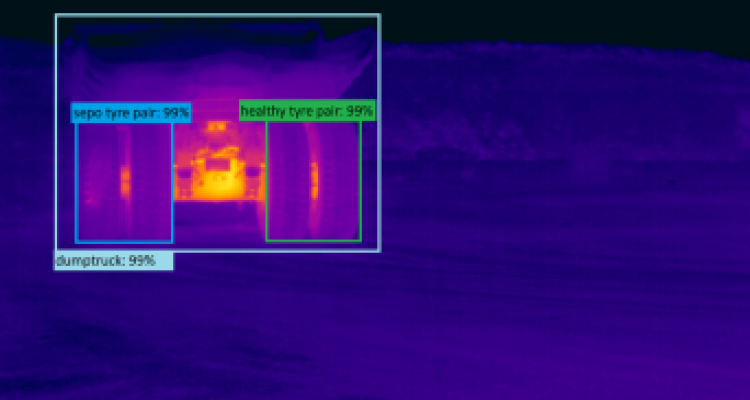
Figure 1: Thermal Monitoring of Flare
Thermography of Flames and Flares
What connects flames and flares is the fact that although they emit IR radiation, they are not objects. They are not defined by a clearly delimited external surface. As a result, there are a number of key concerns regarding the measurement of flame/flare temperature using an IR camera.
- Digital values (or counts) vary linearly with radiance.
- The target is opaque (no transmission through it). In this case, there are only two parameters to consider - emissivity and reflectance. A flame/flare is absolutely not an opaque target, but a semi-transparent one. There is a region in MWIR where a flame is quasi transparent (3,9µm -through flame filter). But there is no wavelength for which a flame is opaque, except maybe in the presence of a lot of unburnt particles, soot, etc.
- Flames and flares radiate like a gas with some rays. An equivalent emissivity would depend on the density of CO2, the temperature and obviously the spectral transmittance. Grey hypothesis is always verified when using a narrow band filter.
- The reflection at the surface of a flame or a flare can be neglected.
- It should be accepted that the reflected radiation of the foreground environment (radiation which is reflected by the object) is the same from all directions, and can be expressed with a black/grey body approximation. Therefore, it can be described by a single temperature.
- Similar to the flame/flare, the atmosphere contains a lot of CO2. What differs is the temperature level – low for the atmosphere vs. high for the rest. Selecting a common wavelength of absorption would make a calibration very sensitive to atmospheric CO2 content.
- Constant atmospheric temperature cannot be considered on long distances.
Of particular importance is the shape of the following graph, which indictaes the radiant intensity of an exhaust plume (taken to be similar in profile to flames and flares) at different wavelengths.

Solutions
From the figure above, the deep and rather broad absorption band of carbon dioxide around 4.25 µm seems to offer a good opportunity to measure the temperature of flames and flares since they contain high concentrations of CO2. However, there is an issue with this type of measurement, as the identical nature of both emission and absorption spectra means the carbon dioxide in the measurement path (i.e. the atmosphere) will absorb the emission from the carbon dioxide in the flame/flare. Also effective calibration can alleviate this problem to some extent, if the real path differs from the path used in calibration, this presents a source of error. The reasons for the difference between these paths can include; the length of the path, its CO2 concentration, or the temperature (or a combination of all three).
It might give good enough results at very short distance with a flame/flare structure that is very stable in time. In general, a narrow band filter at 4.25 µm is a good solution for detection of CO2 emission at short distances (maximum a few meters) where the atmospheric absorption is still at reasonable values. But it is not adapted for measurements.
Whatever the distance, the emission of CO2 at a high temperature is also detectable. The width of a gas absorption band – and by that the width of the emission spectrum – increases with the temperature of the gas. The hot CO2 of the flame/flare will therefore have a broader emission spectrum than the absorption spectrum of cold CO2 in the measurement path. The emission band will be attenuated, mainly in the middle, while the outskirts will be less damped. The figure above shows the measured spectral radiant intensity from an exhaust plume at a long distance. Note that the emission is completely extinguished in the middle of the CO2 band, while two narrow emission bands remain on each side. These two spikes are called Blue Spike, at 4.18 µm, and Red Spike at 4.50 µm. Obviously the second one is larger than the other.
Red Spike filter is commonly installed in cameras, and its calibration is fairly easy. A single calibration time (ca. 80 µs) is often enough to cover a range 450 °C > 1950 °C (Red Spike + ND1).
Radiance Measurement
The radiance unit is built-in for all FLIR ATS-US cameras (RBF calibration at fixed integration times). That same unit is available for FLIR ATS-FR and FLIR ATS-SWE cameras (HyperCAL calibration), once the integration time(s) is(are) determined. See RIR4 - Radiance from CNUCdata.
Note that the displayed radiance is at the camera level. For long distances, the mean atmospheric transmittance can be evaluated by software (Lowtran, Modtran, other model) and then the radiation emitted by the object can be recalculated.
Temperature Measurement
If the flame is of blackbody-type, because of particles and/or soot, then its emissivity is 1. But the apparent temperature corresponds to that of the outer surface and not the core. For an evaluation (not true absolute measurement) at a very short distance (approximately 2 meters), FLIR suggests the following procedure. Two narrow-band filters are needed: one at 3.9 µm, and another one for CO2 (4.25 µm or Red Spike).
A. Make sure that the flame is spatially and temporally stable.
B. Place a thermocouple inside the flame, and take the temperature value given by its controller.
C. Select the through flame filter at 3.9 µm. Aim at the thermocouple with a ROI, and adjust the emissivity (assumed high because thermocouple is oxidized) so that camera gives the same temperature as thermocouple controller.
D. Then, switch to CO2 absorption filter. Without changing the location of the ROI, and assuming that the thermocouple and the flame have the same temperature, adjust the emissivity in order to get the same temperature as the thermocouple controller. You then get the local apparent emissivity of the CO2, which can be used elsewhere.
It must be noted here that we assume that the object is located where the flame is opaque. But this location does not exist! Then, we assume that the apparent emissivity is the same anywhere in the flame. In any case, this is more for comparing different combustion settings rather than for accurate absolute temperatures, and only in a laboratory. In the case the distance is very long, the flame duration is very short. Also, the density of CO2 is changing very quickly. It is, therefore, best to consider radiance and not temperature.